
Over the last few years, we have witnessed a significant transformation in the AEC (Architectural, Engineering and Construction) industry. The interrelationships between building information modeling (BIM) on the one hand, and geospatial, or geographic information system (GIS), technologies on the other hand, have been gradually increasing. By integrating GIS and BIM, planners can generate digital twins to visualize projects from any perspective, improving stakeholder communication and participation. Thanks to this digital twin representation, stakeholders can easily see what the project will look like in “real life” – not only taking into account the terrain, but also the surrounding infrastructures (including underground infrastructures), and the overall general environment in which the project will reside Read more
Collating inputs from various disciplines makes the models even more realistic, enabling better solutions for planning and designing that allow the construction, operation and maintenance of large-scale geographically spread infrastructure in a sustainable manner. In addition, costs decrease because costly, and time-consuming, errors are avoided.
However, to fully exploit and reap all the benefits of GeoBIM, it is important to understand the related Geospatial (GIS) and BIM concepts. Here we briefly explain the concepts behind 3D GIS and BIM, based on open standards and vendor neutral technologies.
CityGML and IFC
In most cases, two standardized data formats, from the two most prominent semantic 3D modelling formats for buildings, are used in the AEC industry: (i) City Geography Markup Language (CityGML), used in the field of 3D GIS, and (ii) Industry Foundation Classes (IFC), an open data model for Building Information Modeling (BIM).
In 3D GIS, CityGML is an open standardized data model and exchange format to store digital 3D models of cities and landscapes. It is published by the Open Geospatial Consortium (OGC) and defines ways to describe most of the common 3D features and objects present in cities, such as buildings, roads, rivers, bridges, vegetation and city furniture, and the relationships between them. It also defines different standard levels of detail (LoDs) for the 3D objects, which allow the depiction of objects for different applications and purposes, such as simulations, urban data mining, facility management, and thematic inquiries.
In BIM, the Industry Foundation Classes (IFC) data model is a neutral and open specification that is not controlled by a single vendor or group of vendors. It is an object oriented file format, with a data model developed by buildingSMART, to facilitate interoperability in the AEC industry. It is a commonly used format for collaboration in projects related to Building Information Modeling (BIM). IFC models everything – from the individual components up to building. CityGML, on the other hand, defines five Levels-of-Detail (LoDs) for building models, where each level then describes what geometric and semantic representations are expected.
1. Concept of Level of Detail (LoD) in CityGML
Level of Detail (LoD) is an important concept in 3D city modelling that defines the degree of abstraction of real-world objects. It is primarily designed to optimize the amount of details of real-world objects by considering specific user needs, computational elements, and economical aspects. CityGML provides a standard model and mechanism for describing 3D objects with respect to their geometry, topology, semantics, and appearance. Based on these parameters, it defines five different levels of detail as illustrated in Figure 1.
.png?width=1318&name=thumbnail%20(1).png)
Figure 1: The five LODs of CityGML 2.0.
Description of LODs in CityGML version 2.0.
Both the geometric detail and the semantic complexity increase from LOD0 up to LOD4, that contains indoor features. In all LoDs, it is possible to map textures onto the structures.
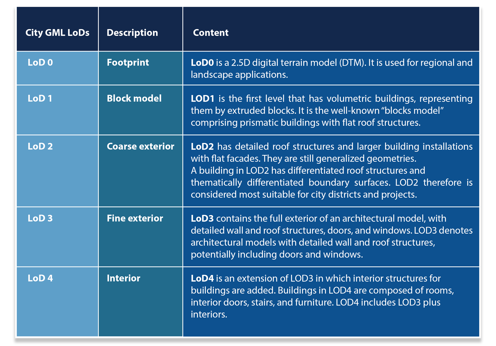 Table 1: Level of Detail
2. Concept of Level-of-Development (LOD) in BIM
In IFC, the Level of Development (LOD) framework is used to specify how much a BIM element has developed. They are helpful for communication and coordination since they can be used to indicate stages or milestones.
The acronym Level-Of-Development (LOD) (capital ‘o’) in BIM, that indicates the state of development from conceptual (LOD 100) to as-built (LOD 500), is therefore not to be confused with Level-of-Detail in CityGML. As mentioned before, LoD in City GML defines the degree of abstraction of real-world objects.
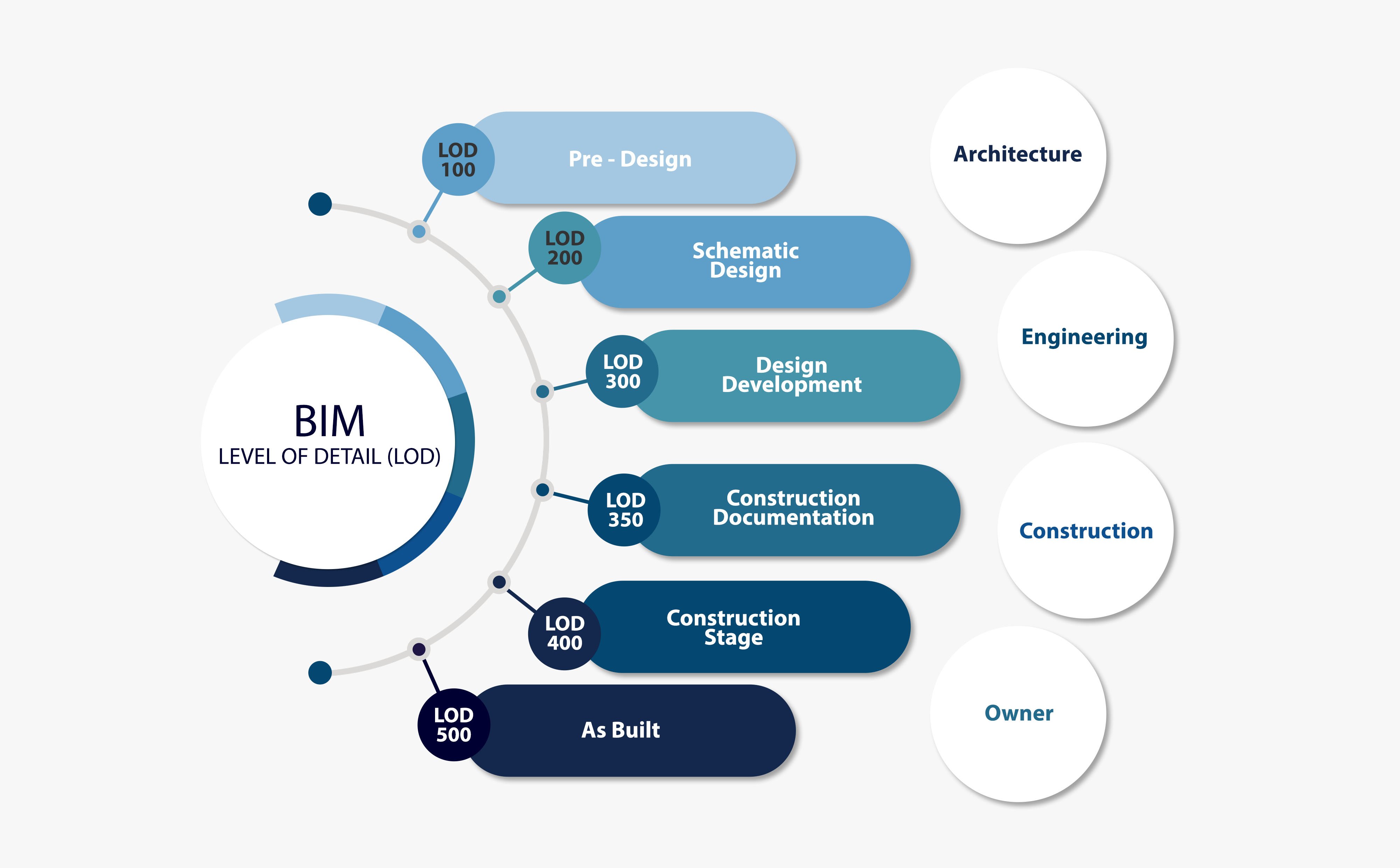
Figure 2: Level of Development in BIM
As the LOD increases, the level of detail and the information contained in BIM elements increase as well. The features of building components at each LOD stage are listed below.
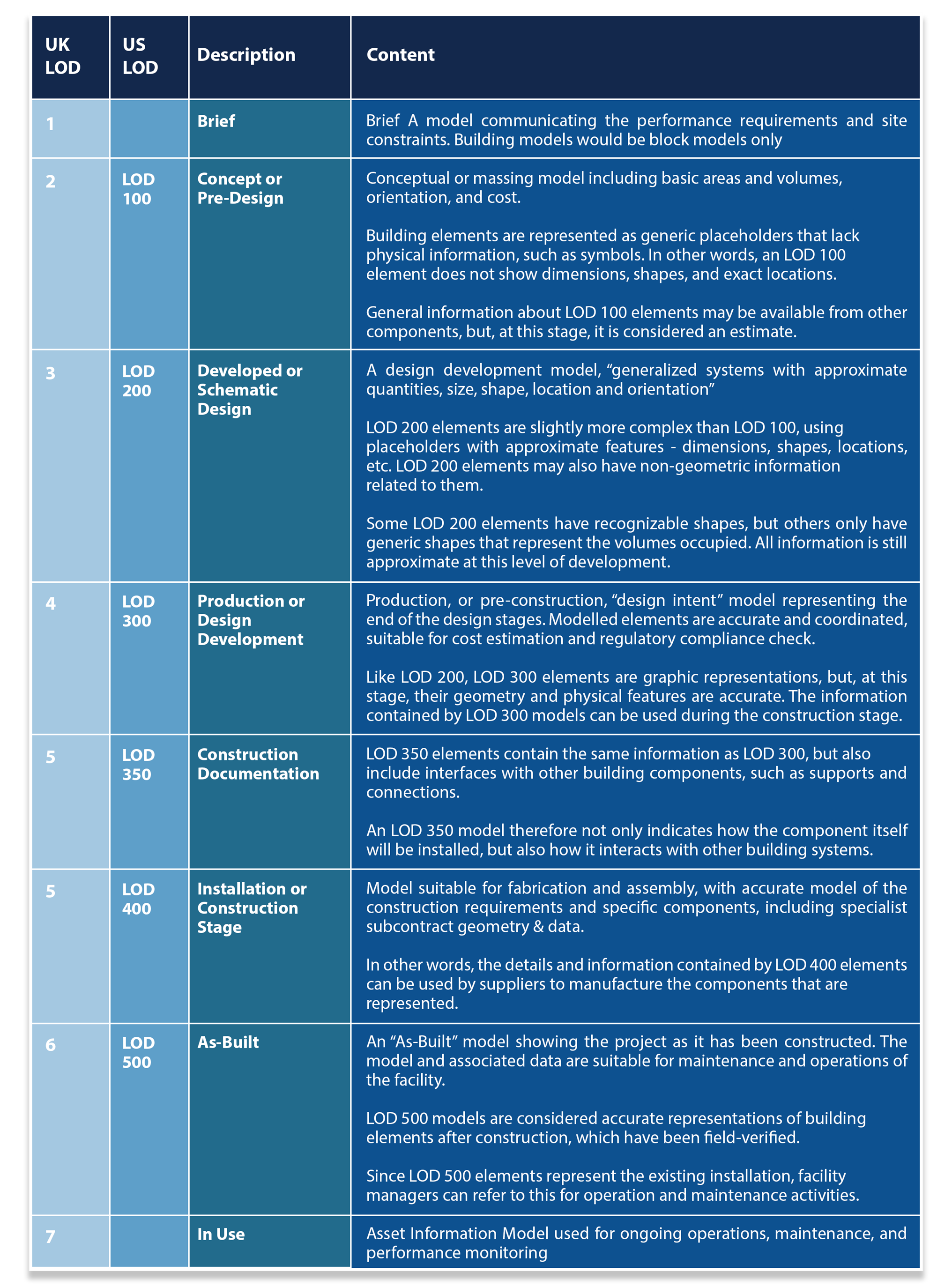 Table 2: Level of Development
3. Differences between CityGML and IFC data
Despite apparent similarities between CityGML and IFC formats at a high level, there are major differences between the two. The conversion to CityGML involves both geometric calculations and the mapping of semantics. While IFC models are built using mostly primitives and swept solids in combination with Constructive Solid Geometry (CSG), CityGML only uses Boundary-representation, as illustrated in Figure 3, B-rep, CSG, and Sweep volumes.
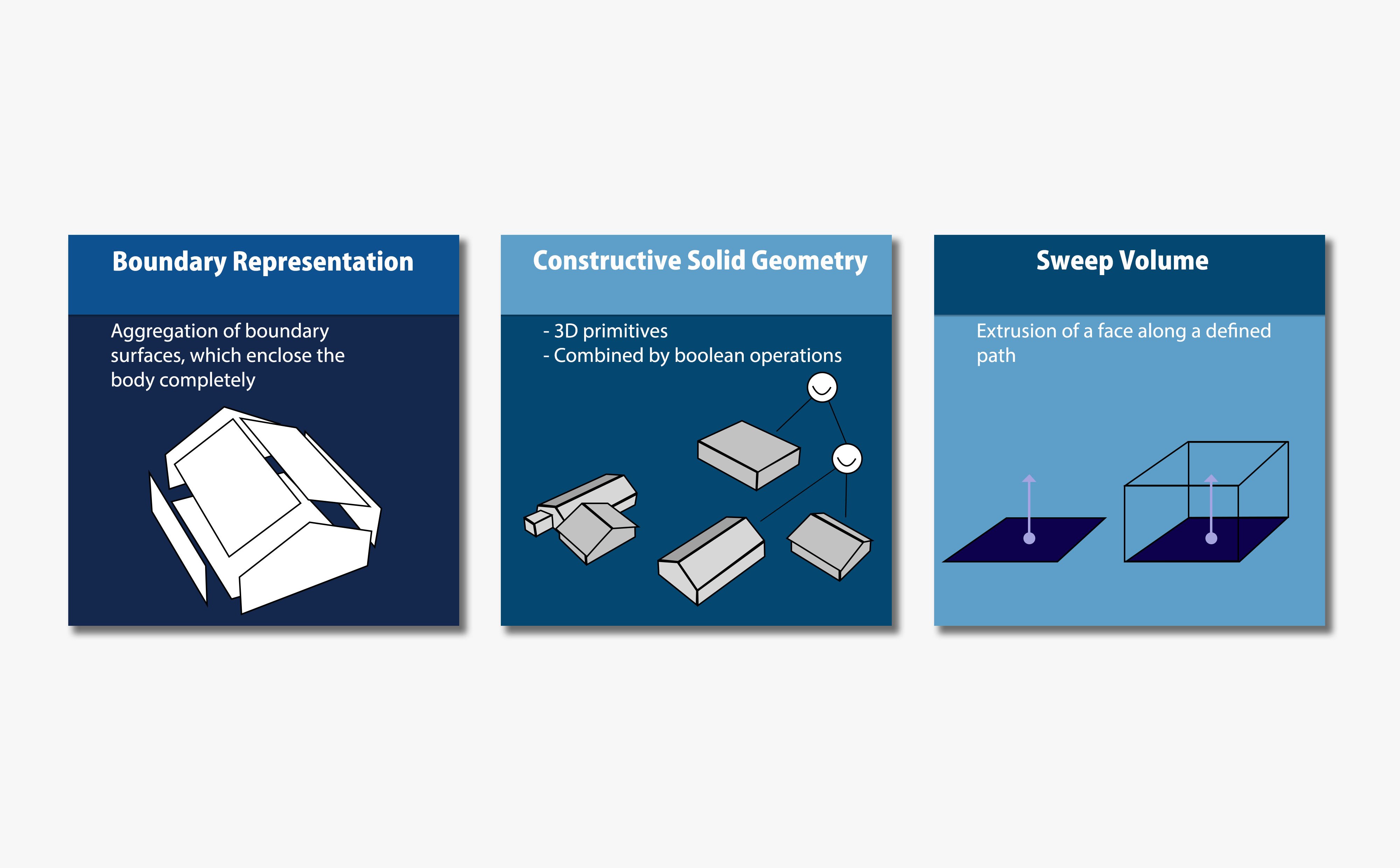
Figure 3: The three possible approaches for representing 3D objects in FIC
- B-rep – B-rep represents a solid body by planar faces that are located at the boundary of the body and completely enclose the body. Each face acts as the border between what is inside and outside the body.
- CSG – CSG is used to create solid bodies by one or many Boolean operations on base solids. A Boolean operation between two geometries generates a new geometry which can, for example, be the union, difference or intersection, as illustrated in Figure 4
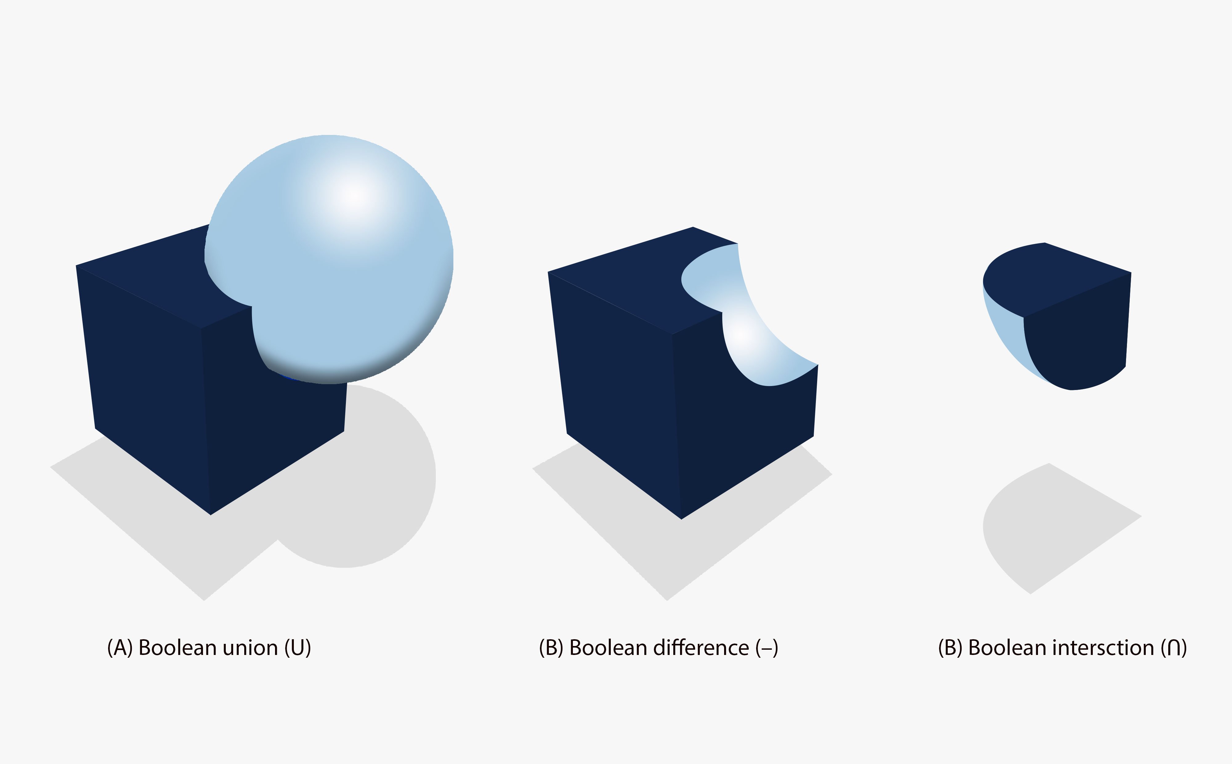
Figure 4: Boolean operations between a cube and a sphere
- Sweep volumes – Sweep volumes define a solid body by a 2D profile and a path. The geometry of the body is computed by moving the profile along the path. The 2D profile can be a primitive shape, such as a disk or a polygon, and the sweep can either be a linear extrusion or a rotational sweep, where the path is defined by an axis and an angle.
The geometry of the latter two types are stored implicitly, meaning that the geometry is generated by calculating parameters. An IFC viewer/reader must apply the sweeping and CSG computations before being able to visualize or use the objects. Figure 5 illustrates an example of this for implicit CSG geometry. The figure also depicts how, at the same time, the relations between a door and a wall are stored.
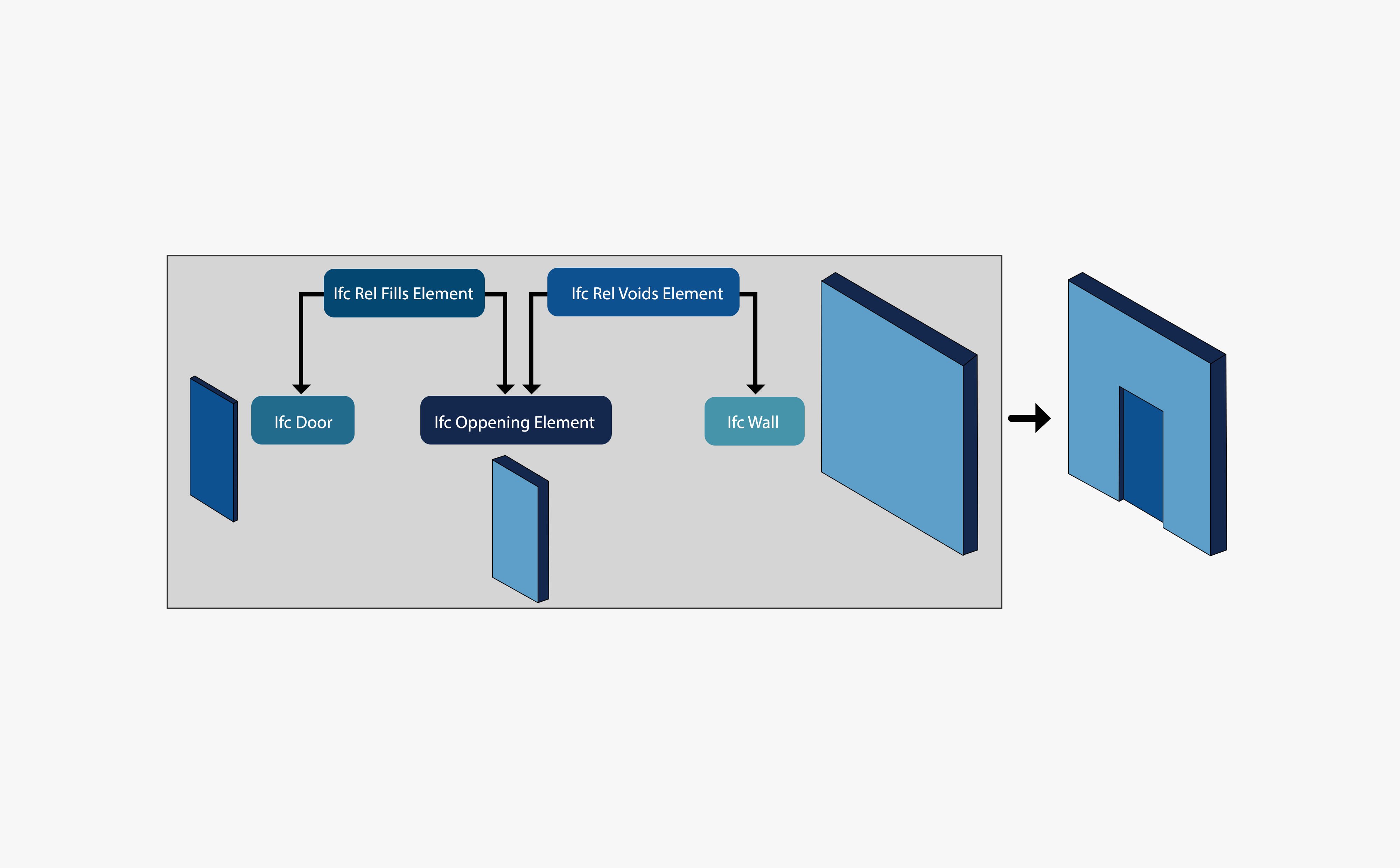
Figure 5: An example of implicit geometry: the wall is cut by the opening element using the Boolean difference. The door is then placed within the gap in the wall.
Calculating the explicit B-rep geometry does not yield a unique solution. For e.g., a disk should be converted to a regular polygon, but the number of sides of the polygon depends on the converter. For the purpose of creating valid CityGML geometries, it is sufficient to have the geometry correctly representing the original model. Although there are three geometric models, in practice, most IFC models are built using sweep volumes and CSG.
One difference between IFC and CityGML is that in IFC, implicit geometry refers to the geometry that is implied by the parameters stored in the IFC file and the definitions in the IFC Object Model specification. In contrast, according to the CityGML standard, implicit geometry is geometry that is stored once, as a template, and can then be reused multiple times by referring to it.
Conclusion
To successfully integrate GIS and BIM, and thus fully reap the benefits of GeoBIM, a good understanding of the related GIS concepts on the one hand, and the related BIM concepts on the other hand is key. Thanks to our experience, knowledge, and expertise in the domain of GeoBIM, Avineon has built this understanding. We help your project planners, designers, and developers generate the digital twin that they need to visualize their projects in the real world, allowing your organization to experience the benefits of more sustainable and cost-effective project planning and execution.