

In this increasingly digital society, more and more companies and governments are accelerating their digital transformation by adopting 3D city models and digital twins. They are, to an increasing extent, becoming an important part of contemporary (city) management, unlocking a wide variety of new possibilities.
The importance of enhanced 3D building data
In the context of “smart cities”, we currently see that 3D city models and digital twins are being used in various domains, such as safety, mobility, and tourism. A couple of concrete examples include noise modeling, shadow analysis, urban development visualizations, and risk management by calculating and simulating emergency scenarios (e.g. floods, power failures, etc.).
In order to enable these advanced types of calculations and visualizations, it is required that the individual buildings in the 3D city model have a sufficiently high level of detail, including, for example, characteristics for all roof and wall surfaces. By augmenting your already existing 3D city model through object detection algorithms, we can now add additional details on energy characteristics, such as roof windows or existing solar panel installations.
Combining this enriched content with characteristics such as roof volume, surface, orientation, and/or slope, enables calculations on energy efficiency and energy saving potential. Curious how? Then keep reading!
Source data
Avineon recently conducted a pilot project in the domain of object detection. Our main objective was to generate estimates for the location, size, and contour lines of roof objects, such as windows and solar panels, through artificial intelligence (AI) with minimal man-machine interaction.
The pilot area was located in Roeselare, a town in Belgium with 60 000 inhabitants and 45 000 buildings, consisting of two test areas of five square kilometres, each with about 500 buildings (Image 1).
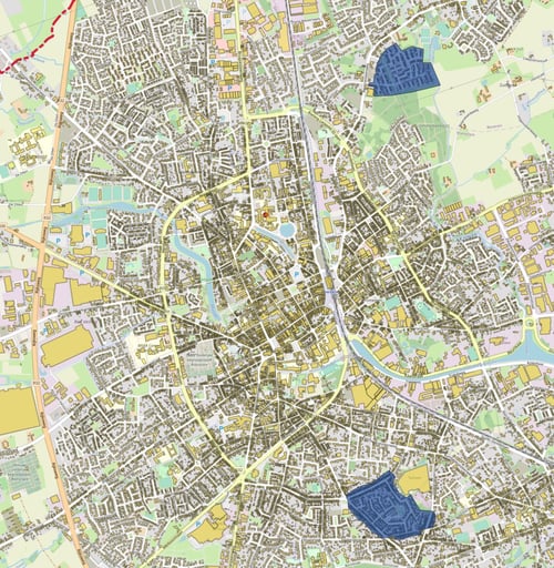 "Image 1: Map of Roeselare showing the building stock footprints. The two pilot areas are marked in blue."
To conduct this pilot project, we had both aerial imagery and highly accurate 3D representations of the buildings (and roofs) available. We started from high-resolution (3cm) ortho images and, as part of the project, created a textured 3D representation of the buildings, using both stereo and oblique imagery (Images 2 and 3).
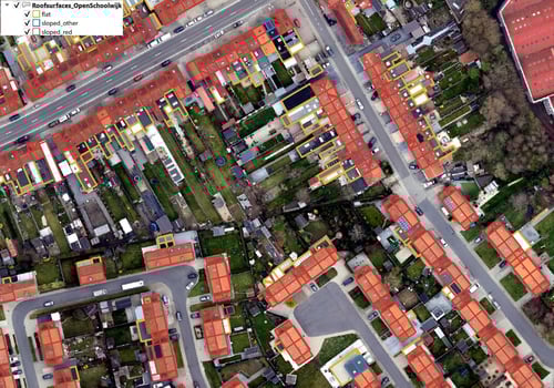 "Image 2: Birdseye view on test area 2 ("OpenSchoolwijk"). Ortho image with roof outlines marked in red, blue, or orche, depending on the roof type (flat, red sloped, or other sloped roofs)."
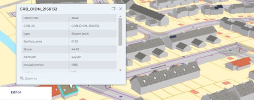 "Image 3: Screenshot webviewer "OpenSchoolwijk"."
Thanks to the detailed geometry of the roofs included in the 3D model, we were able to create algorithms that are both efficient and explanatory. In the next two paragraphs, we will focus on explaining the functionality of our algorithms and on showing the results. To limit the length of this article, we will only cover the detection of windows, but the same methodology can be extended to the detection of solar panels.
Value and colour contrasts
A brief look on the roofs in test area 1 shows that we should be able to detect most of the windows because of a clear difference in “value” with the surrounding roof texture, a terminology we borrow from photography to indicate the range of light and dark tones on an image.
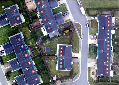
The building stock in this test area is quite uniform, mainly consisting of buildings with dark blue or grey roofs, while the windows often have much lighter (blue) tone values (Images 4 and 5).
 "Image 4: Birdseye view on area 1, showing a building stock with roof textures with dark tone values."
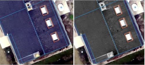
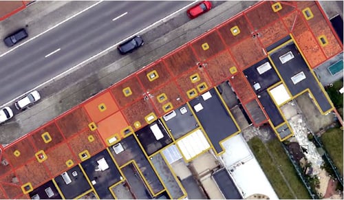
"Image 5: Close-up view on a building of area 1: RGB colour vs. greyscale value contrast."
The orange contour lines on "Image 5" were generated by our algorithm. In this case, value contrast alone was sufficient to predict accurate window geometries. This is, however, not the case anymore for the second test area within the pilot area. Test area 2 is, statistically, quite different from test area 1, as there are many more red sloped roofs in test area 2 (Table 1).
| Roof Type | Test Area 1 | Test Area 2 | ||
| Total Area (ha.) | Percentage | Total Area (ha.) | Percentage | |
| Sloped, red | 0,90 | 31,0% | 3,87 | 63,8% |
| Sloped, other | 1,71 | 59,1% | 0,93 | 15,3% |
| Flat | 0,29 | 9,9% | 1,26 | 20,9% |
| Total | 2,90 | 100% | 6,06 | 100% |
"Table 1: Roof types in test area 1 vs. test area 2."
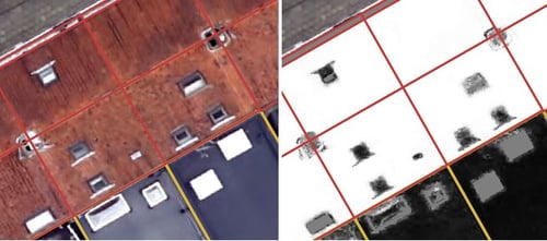
Although the windows on the red roofs are easy to spot with the human eye, this is not the case when detecting windows through the value contrast logic explained above. On “Image 6” (here below) we, for example, notice two windows that share a similar shade of grey with the surrounding roof, and are hence very hard to detect on the greyscale image.
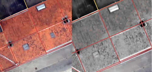 "Image 6: RGB colour image vs. value contrasts of the same scene."
Such cases were quite common in test area 2 and hence require a different approach. Here, we will clearly have to rely on the colour contrast in the RGB image to generate contour lines for roof windows.
An implementation of object detection in FME
Replicating these seemingly trivial observations from the previous paragraph in a computer is not that straightforward. However, thanks to the realistic capturing of the roof geometry, consistent with the roof contours on the ortho image, we are able to generate estimates without the need for overly complex calculations.
As a first step to quantify the observations from previous paragraph, we select a roof surface (Images 7 and 8), and then create a histogram of the intensity values for all its pixels.
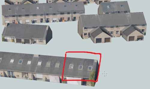 "Image 7: Location of the selected roof, captured in 3D."
 "Image 8: Close-up view on the ortho image of the highlighted roof surface."
We extract the pixels from the roof background on a histogram in dark blue, and add the pixels from the windows in light blue. Although there is some overlap, we can see that, in general, window pixels have much higher values than those of the roof background (Image 9). This value contrast can be used to separate the windows from the roof backgrounds and, by doing so, extract the window geometry from the rest of the roof surface.
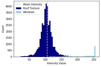 "Image 9: Histogram of the intensity values of the selected roof surface."
Since each roof has its own colour and tone value, it is impossible to define one unique value range that is valid across all roofs. We, however, found that the mean intensity value often serves as a good estimate for the roof texture value. Based on this, we created a standard for measuring the value contrast of all roof surfaces.
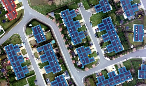
As a next step, we implemented this methodology in an FME workflow, adding additional conditions on the geometry of our predictions to filter out erroneous geometries caused by occasionally extreme intensity values of pixels on the roof background itself. By doing so, were able to detect nearly 93% of the windows in test area 1, while keeping the “false positives” at a minimum (Image 10).
 "Image 10: High window detection rate in test area 1, using the value contrasts between roofs and windows."
In test area 2, our algorithm performed well on flat roofs, detecting 86% of the roof windows. The overall detection rate, however, dropped to almost 60%, which indicated that we needed to separate the red roofs from the analysis and adapt our algorithm to extract window geometries by using the colour contrast between roofs and windows (red), instead of using the value contrast (blue/grey) (Image 11).
 "Image 11: Using value contrast, detection rates drop for red sloped roofs in test area 2, but most windows on flat roofs are still detected."
Although there are multiple ways to measure the colour contrast in an image, we choose to generate a grey scale image from the original RGB image, in which red pixels are represented in light tone values and other colours are represented in darker tones (Image 12).
On this greyscale image, we then apply the same value contrast techniques as described before, increasing the detection rates for the red sloped roofs to 90% (Image 13).
 "Image 12: Red colours have lighter tones on the greyscale image to the right."
"Image 13: Increased detection rates on red sloped roofs, using colour contrast."
Conclusions and future work
Adding this additional information on roof windows and solar panels to your already existing 3D city model unlocks powerful perspectives in terms of analyzing and visualizing both current and future policy scenarios with regard to energy efficiency, climate change, urban growth, etc., as part of climate action plans. We can detect these automatically, via AI, and then create 3D polygons that perfectly match the roof (location, orientation, slope).
Now that we have established a way to extract accurate geometries for windows on roof surfaces, by using the roof outlines of the 3D model to clip the ortho image and then analyse the value and colour contrasts, we are currently looking into generalizing similar techniques for the detection of windows and doors on wall surfaces.